Built with an ergonomic design and intuitive interface, this multifunction installation tester provides standard electrical installation testing and specialized functions like programmable autotest, GFCI, and insulation PreTest. Moreover, it includes integrated data management and is compatible with Fluke Connect for extensive reporting.
Built with an ergonomic design and intuitive interface, this multifunction installation tester provides standard electrical installation testing and specialized functions like programmable autotest, GFCI, and insulation PreTest. Moreover, it includes integrated data management and is compatible with Fluke Connect for extensive reporting.
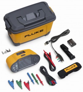
The Fluke 1670 Series Multifunction Installation Testers will revolutionize the way you work. With an ergonomic design, seamless user interface, integrated data management capabilities, wireless connectivity, and comprehensive reporting software, the 1670 Series sets the new standard for an integrated installation testing solution.
Reliable installation testing is essential for ensuring the safety, optimal functionality, and integrity of a facility’s electrical systems. The 1670 Series' rugged design allows you to verify the safety of electrical installations in domestic, commercial, and industrial applications while meeting the requirements of IEC/HD 60364-6 and all relevant local installation test standards.
With the 1670 Series, you’ll be able to perform your required testing faster and reduce the time you spend on documentation, all while having the ultimate confidence in the data you’re collecting.
Features
Simplified user interface and testing setup
The 1670 Series takes data management to the next level streamlining test set up and preparation with an advanced bidirectional user interface. When setting up your project, the hierarchical tree topology for clients, sites, distribution boards, circuits, and test points can be easily customized using the high-resolution colour touchscreen, a smart device, or by PC. Edit, add, delete, or modify information directly on the tool as you test to ensure accurate data, or transfer updates to your tester via the TruTest™ desktop software (sold separately). Easy-to-read test tables help you quickly see that you are capturing the right measurement data at the right test point, every time. Now you can spend less time setting up your tester and organising data, giving you more time to perform valuable testing.
Perform all required tests up to 30% faster
Installation testing can be a time-consuming process. It often requires repetitive, manual test setups that can be frustrating and introduce the opportunity for errors.
The Fluke 1670 Series leverages a unique Auto Test function that enables you to run through an entire installation test sequence at the touch of a button. An integrated help function provides a visual connection guide to help ensure measurement success. Automatic measurement validation, with user-defined limit warnings, compares test results to the relevant standards and provides you with an immediate visual pass/fail indication to quickly identify potential issues. Eliminating manual testing and automating measurement validation means you can perform your tests up to 30% faster, giving you more time to focus on other critical tasks and increasing your productivity
Faster installation testing and documentation in three easy steps
1. Setup: The simplified bidirectional user interface to quickly and easily setup your tester using the color touchscreen, a smart device, or by PC
2. Test: Perform all your required testing up to 30% faster using the unique AutoTest function and Automatic Measurement Validation, giving you immediate visual pass/fail indications
3. Report and document up to 50% faster. Automatically link test results, preview inspection results in the field, and generate test certificates on site at the touch of a button
Reduce Documentation and Reporting Time up to 50%
The Fluke 1670 Series Multifunction Installation Testers help you reduce documentation time by up to 50%. Link test results to the circuit or point under test, reducing manual data entry and recordkeeping. You can also preview inspection results in the field via the tester, a smart device, or PC, and Fluke Connect compatibility making it easy to store, manage, and share your data from the field. Fluke TruTest Software (sold separately) lets you generate inspection certificates on site with just a few simple steps, so you can finalise and invoice your inspection at the time of service. The Fluke Connect mobile app enables you to document and input all relevant photos and inspection notes, so you can complete your work on site, eliminating extra work at the office.
Insulation Pretest™ functionality
The Fluke 1674 FC includes a patented Insulation PreTest, so you can better protect the installation and avoid costly mistakes. If the tester detects that appliances are connected to the system during the test, it will stop the insulation test and provide a visual and audible warning. This helps eliminate accidental damage to peripheral equipment and saves you both time and money.
Optimized software and reporting
Fluke TruTest Software (sold separately) simplifies electrical system data management and reporting, eliminating the hassle of traditional data management with a single, integrated Fluke solution. Proper data management and testing information is critical for producing easy-to-understand reports for clients or your management team. TruTest streamlines the process by allowing you to create and transfer testing metadata between the software and your installation tester using a USB-C interface cable, or via the Fluke Connect mobile app, which helps you ensure accurate results.
The user-friendly interface, intuitive workflow, and report builder means that you can quickly format your measurement data into printable test certificates and reports, complete with your company logo and electronic signature. The live onscreen dashboard allows you to see the status of all your clients instantly and navigate to further levels of detail if desired.
Fluke TruTest Software (sold separately) allows you to create certificates that are compliant with a growing list of regional reports, including BS7671, DIN VDE 0100-600, ÖVE/ÖNORM E 8101, NIN/NIV, NEN3140, and other European installation test standards. All these reports are available at the touch of a button, and a pre-configured international template ensures that no matter your location, TruTest Software has you covered.
Fluke connect compatibility
Enhance the functionality of this Installation Testers with the Fluke Connect mobile app, eliminating tedious data entry and optimizing data management with cloud storage. The Fluke Connect mobile app wirelessly synchronizes measurement data from your installation tester for later export to TruTest desktop software (sold separately), allowing for prompt and effective reporting even on location. Use the Fluke Connect app to create projects and upload them to your 1674 FC for streamlined data management. Construct distribution boards and circuits to send to your tester, using this data to guide your testing regime. With the Fluke Connect app, you can also take photos with your smart device and assign them, along with notes, to specific test points or assets, creating detailed visual inspection reports.
With the powerful Fluke Connect ecosystem of test tools, you’ll be able to take your troubleshooting and reporting to the next level. Connect additional test tools, like the Fluke 369 FC Leakage Current Clamp or the Fluke 1630-2 FC Earth Ground Clamp, to synchronize data between auxiliary devices and test points, providing your clients with a clearer picture of overall facility health.
Applications
| Insulation pretest | Insulation safety pretest: Connections from the Tester to L, N, and PE are required |
| Voltage measurement AC, DC and Frequency | Range: 600 V Resolution: 0.1 V Input impedance: 320 kΩ Overload protection: 660 V Range: 45 to 66 Hz Resolution: 0.1 Hz Input impedance: 320 kΩ |
| Continuity testing (RLO) | Range (auto ranging): 20 Ω/200 Ω/2000 Ω Resolution: 0.01 Ω/0.1 Ω/1 Ω Open circuit voltage: >4 V |
| Insulation resistance measurement (RISO) | 50-100-250-500-1000 V |
| Insulation resistance measurement (RISO) | Test voltage: 50 V Insulation resistance range: 10 kΩ to 50 MΩ Resolution: 0.01 MΩ Test current: 1 mA @ 50 kΩ Test voltage: 100 V Insulation resistance range: 10 kΩ to 20 MΩ Resolution: 0.01 MΩ Test current: 1 mA @ 100 kΩ/20 to 100 MΩ Resolution: 0.1 MΩ Test voltage: 250 V Insulation resistance range: 10 kΩ to 20 MΩ Resolution: 0.01 MΩ Test current: 1 mA @ 250 kΩ/20 to 200 MΩ Resolution: 0.1 MΩ Test voltage: 500 V Insulation resistance range: 10 kΩ to 20 MΩ Resolution: 0.01 MΩ Test current: 1 mA @ 500 kΩ/20 to 200 MΩ Resolution: 0.1 MΩ 200 to 500 MΩ Resolution: 1 MΩ Test voltage: 1000 V Insulation resistance range: 100 kΩ to 200 MΩ Resolution: 0.1 MΩ Test current: 1 mA @ 1 MΩ/200 to 1000 MΩ Resolution: 1 MΩ |
| Insulation Monitoring Devices (IMD) IEC 61557-8 | Range: 1 to 10 kΩ Resolution: 1 kΩ Range: 10 to 100 kΩ Resolution: 10 kΩ Note: > 1 MΩ only available with voltages >100 V |
| Loop and line impedance (ZI No Trip and Hi Current) | Range: 100 kΩ to 3 MΩ Resolution: 100 kΩ Range Setting: 10 Ω[2] Resolution: 0.001 Ω Accuracy: Hi Current mΩ mode: ± (2% + 35 digits) No Trip (2&3 wire) mode: ± (3% + 6 digits) Range Setting: 20 Ω Resolution: 0.01 Ω Accuracy: Hi Current mode: ± (2% + 4 digits) Range Setting: 200 Ω Resolution: 0.1 Ω Accuracy: No Trip mode: ± (3%) Hi Current mode: ± (2%) Range Setting: 2000 Ω Resolution: 1 Ω Accuracy: ± 6%[3] Note: [2] Fluke Connect™ 1674 FC model only. [3] Valid for mains voltage > 200 V |
| Prospective Earth Fault Current (PEFC) Prospective Short Circuit Current (PSC) | Range: 0 to 50 kA Range: IK < 1000 A Resolution: 1 A Range: IK ≥ 1000 A Resolution: 0.1 kA |
| Voltage drop (by line impedance test) | Range: 0.0 to 99.9% Resolution: 0.1% Accuracy: Consider accuracy of line impedance measurement(s) |
| RCD tests, RCD types tested | RCD Type: Yes AC[2] G[3]: Yes AC S[4]: Yes A[5], F[6] G: Yes A, F S: Yes GFCI Note: [2] RCD tests permitted only if the selected current, multiplied by earthing resistance, is < 50 V. [3] AC – Responds to AC [4] G – General, no delay [5] S – Time delay [6] A – Responds to AC and pulsed signal |
| RCD tripping time test (ΔT) | RCD tripping time test (ΔT) Test Function 10 mA: x½, 1, x5, Ramp, Auto 30 mA: x½, 1, x5, Ramp, Auto 100 mA[1]: x½, 1, x5, Ramp, Auto 300 mA[1]: x½, 1, Ramp 500 mA[1]: x½, 1, Ramp 1000 mA[2]: x½, 1, Ramp Var[3] x½, 1, Ramp Note: Mains voltage 50 V – 265 V ac, 45/66 Hz [1] Type B RCDs require mains voltage range of 195 V to 265 V. [2] Type AC RCDs only. [3] Type A RCDs are limited to 700 mA, not available for Type B RCDs. |
| RCD Tripping Current (IΔN) Measurement/Ramp Test | Current range: 30 to 110% of RCD-rated current Step size: 10% of IΔN Dwell Time Measurement Type G: 300 ms/step Type S: 500 ms/step Accuracy: ±5% |
| Earth resistance test (RE) 1673 FC and 1674 FC only | Range: 200 Ω/2000 Ω Resolution: 0.1 Ω/1 Ω Frequency: 128 Hz Output Voltage: 25 V |
| Phase sequence indication | Icon: Phase Sequence indicator is active Range: 185 to 600 V Display: “1-2-3”: or “3-2-1” for incorrect phase |
| Power | Battery: BP290, Li-ion, 10.8 V, 2500 mAh, 27 Wh |
| Ingress Protection | IEC 60529: IP40 Safety: Complies with IEC/EN 61010-1, IEC 61010-2-030, IEC 61010-2-034 Safety rating: CAT III 600 V, CAT IV 300 V |
| Performance | IEC 61557-1 to IEC/EN 61557-8 and IEC 61557-10 |
| Dimensions | 10.3 x 5.6 x 4.7" (26.25 x 14.19 x 11.93 cm) |
| Weight | 3.5 lbs (1.6 kg) including batteries |